


A cut-to-fit deck kit looks simple in the box: numbered panels, a layout drawing, a roll of tape. The complexity is all upstream — in how the deck was measured, how the panels were nested, and whether anyone checked that panel 7 lands where the drawing says it will.
For boat builders, refit yards and dealers, the kit is a production part with a tolerance, not a craft project. This article walks the actual chain from deck to box, and names the points where kits go wrong.
A note on numbers. Tolerances and lead times below are typical ranges for production programmes. Confirm the specific values with your supplier’s process capability — boat deck geometry varies enormously, and a narrow beam skiff is not a pontoon.
1. What is in a kit
A properly packed custom deck set contains more than foam:
- Cut panels, adhesive-backed, grouped by deck zone (bow, cockpit, gunwale caps, swim platform)
- A layout drawing showing panel numbers and their positions, at the same revision as the cut file
- Part labels on each panel, or laser marking, so installation does not depend on guessing
- Installation sequence — which panels go down first, and where the seams are designed to land
- Edge trim or sealant if the design calls for it
- A revision identifier tying the kit to one specific deck plan
The revision identifier is the item most often missing and the one that causes the most expensive mistakes. Two deck plans for the same model year, one hatch moved 20 mm, and a kit that no longer fits.
2. Where the geometry comes from
Four input routes, in descending order of reliability:
1. Builder CAD (DXF/DWG). The best case: exact deck outline, hatch positions and hardware locations straight from the design file. Even here, check against the as-built boat — production hulls drift, and the deck the CAD describes is not always the deck that exists.
2. 3D scan. Accurate to roughly a millimetre and increasingly common in refits. The output still needs cleanup: scan noise, hardware, and the decision of where the panel edge should sit relative to a toe rail.
3. Physical template. The standard for refits and older boats. Accuracy depends almost entirely on the material and the technique — see below. Expect a few millimetres of error, which the design must absorb at the margins rather than at the hatches.
4. Trace the removed deck. Useful when replacing an existing pad, provided the old pad had not shrunk or stretched. Measure the deck, not the old foam.
Making a template that survives the mail
- Use dimensionally stable material — mylar or heavy rosin paper, not thin kraft paper that grows with humidity.
- Mark bow and starboard explicitly. Not “front.” Not an arrow you will forget.
- Draw datum lines across the deck and note two cross-measurements in each zone. These catch template distortion before cutting.
- Trace hardware openings (cleats, rod holders, hatch hinges, fuel fills) with their true outline, not a circle approximation.
- Mark hatch swing direction — a panel that interferes with a lid opening is a fit failure even when the outline is perfect.
- Photograph the templated deck before shipping. Photos resolve most disputes in one message.
3. Design rules that decide whether the kit fits
Seams belong at natural breaks.Place them along moulded lines, at the edge of a hatch surround, or where the deck changes plane. A seam running across a traffic lane will lift first and look wrong immediately.
Clearance around hardware.
Typically 3–5 mm around hatches, cleats and fillers, so the panel does not fight the fitting and water can drain. Zero clearance looks tight in CAD and buckles in the sun.
Grain direction.
Emboss direction reads as a design decision across a whole deck. Mixing directions between adjacent panels is visible from ten metres and cannot be fixed after bonding.
Panel size.
Large panels look better but are harder to place without trapping air. If a panel exceeds what one installer can handle with a roller, split it — at a designed seam, not wherever the sheet ran out.
Hatch cut-outs.
A hatch lid is a separate panel. Decide whether the panel sits inside the hatch recess, laps the surround, or stops at the edge — and make that explicit, because it changes the entire layout.
Bleed allowance for refits.
On a templated deck, allowing 2–3 mm where the panel meets a coaming gives the installer somewhere to trim. On a CAD deck, cut to nominal.
4. Nesting, kerf and the cut itself
Nesting is where material cost is decided. A good layout uses 80%+ of the sheet on a typical deck set; a careless one wastes a panel’s worth of sheet on offcuts.
Rules that matter in the nest:
- Sheet edges and grain direction fixed first, then parts rotated only where the grain allows
- Small parts (hatch lids, step pads) packed into the gaps between large panels
- Distance between parts at least the bit diameter plus a margin, so the tool does not deflect
- Adhesive liner kept flat — nesting does not cut the liner through
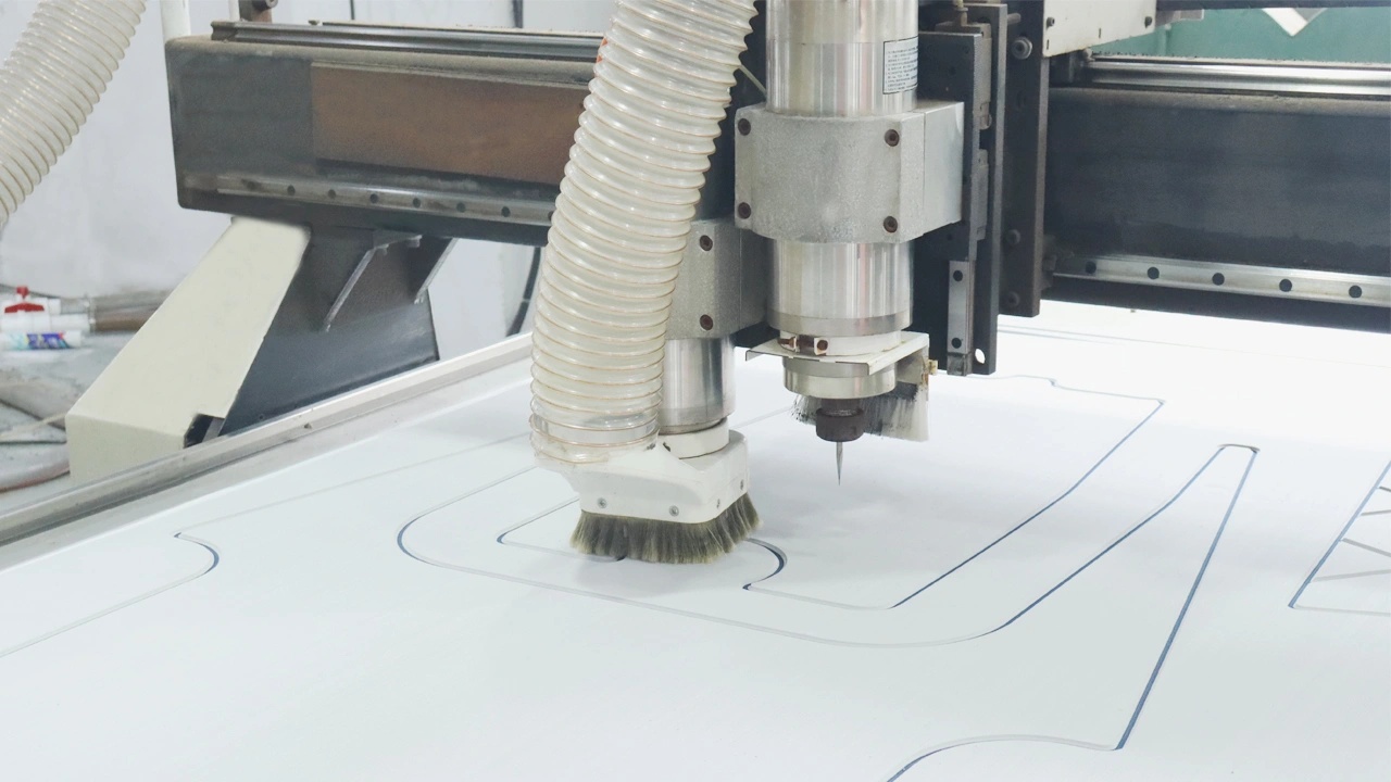
Kerf compensation is the difference between a panel that fits and one that is 3 mm oversize on every edge. The tool path is offset by half the bit diameter; a 4 mm bit removes 4 mm of material, and the CAD outline is the finished edge, not the centreline.
Edge quality matters more than most buyers realize. A sharp bit at the right feed rate leaves a closed, clean edge. A dull bit tears cells, and a torn edge wicks water and stains — visible within weeks on a light-coloured deck.
Typical cut tolerance: ±1–2 mm on a CAD-derived kit, ±3 mm on a templated refit where the source itself carries error.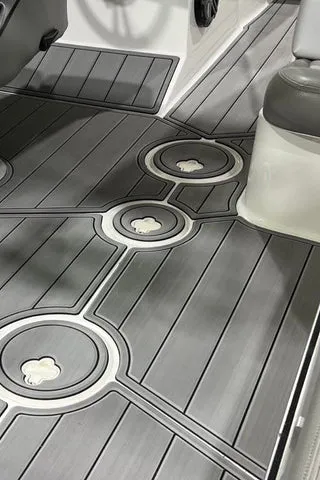
5. Marking and packing
Marking turns a pile of foam into an installation:
- Panel number matching the layout drawing
- Orientation arrow, and “this side up”
- Zone name for multi-zone decks
- Seam reference marks so adjacent panels align at the joint, not just at the outline
Pack flat. Rolling a laminated panel can wrinkle the adhesive liner and put a permanent curve into a part that has to lie flat. Interleave panels, protect edges, and keep the carton dry — a kit that sat in humidity for a week installs badly.
6. Lead time, realistically
For a typical programme:
- Sample or first article: 3–7 working days after approved geometry
- Production run: 10–20 working days, depending on sheet stock and coating
- Revision after a fit issue: treat as a new first article, not a rework — allow the same window
The variable that blows up schedules is not cutting. It is geometry clarification: a template with no datum lines, a hatch drawn as a circle, a CAD file two model years old. Clean input compresses the whole chain.
7. Where kits go wrong
| Failure | Cause | Prevention |
|---|---|---|
| Panels mirrored | Template flipped during digitizing | Mark bow/starboard on template and drawing; dry-fit check |
| Seam drift across the deck | No datum lines; cumulative error | Cross-measurements per zone; seam reference marks |
| Panel overlaps hatch | Opening not traced or hinge swing ignored | Trace true outline; mark swing direction |
| Edges lift within weeks | Panel cut to nominal with no clearance | 3–5 mm clearance; edge sealing where specified |
| Visible pattern mismatch | Grain direction not fixed in nesting | Lock grain in the nest; check adjacent panels |
| Kit does not match second boat of same model | Production variation ignored | First article per hull, or accept a trim allowance |
| Adhesive liner wrinkled | Panels rolled for shipping | Ship flat |
Melors Marine Deck Factory
📧 Email: admin@marinedeckfactory.com
📱 Cel: +86-13699812532
🏭 Address:
Ruiji Industry Zone, Dongao Village,
Shatian Town, Huiyang District,
Huizhou City, Guangdong Province, China.
🌐 Website: marinedeckfactory.com
Transform Your Boat with Melors Marine Deck Now!
Send us your inquiry now and get free samples for testing.
Contact Us Now →8. FAQ
1.Can you cut from a photo?
No. A photo gives shape, not scale. It is useful for confirming orientation and hardware, never for dimensions.
2.How accurate is a paper template?
Typically within a few millimetres if the material is stable and datum lines are used. That is enough for most refits, provided the design leaves a trim allowance at the margins.
3.Do I need to remove the old deck first?
For an accurate template, yes — you are measuring the deck, and an old pad hides the true edges and any substrate damage.
4.Can a kit be installed by the owner?
Yes, and it usually is. The kit removes cutting and layout risk; it does not remove the need for clean surface preparation, which is where most owner installs fail.
5.What if one panel does not fit?
Send the photo and the panel number. With a versioned cut file, a single replacement panel is a small job — which is the main argument for keeping the file, not just the kit.
Bottom line
A custom kit is a manufacturing process with a measurement at one end and a box at the other. The parts that decide success are unglamorous: datum lines on the template, grain locked in the nest, clearance around hardware, and a revision number on the drawing.
Get those right and installation becomes assembly.
Get them wrong and the customer concludes that cut-to-fit decking does not fit.
Send a deck plan, a DXF or a templated outline and we will return a nesting layout, panel schedule and first-article timeline before you commit to a production run.
